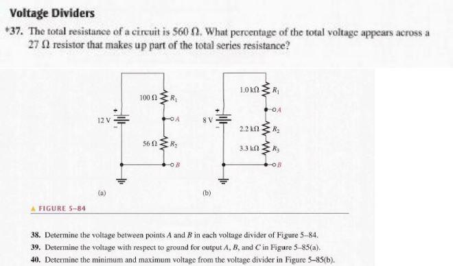
Voltage Dividers 37 The total resistance of a Circuit Diagram
BlogVoltage Dividers 37 The total resistance of a Circuit Diagram One final point about capacitive voltage divider circuits is that as long as there is no series resistance, purely capacitive, the two capacitor voltage drops of 69 and 31 volts will arithmetically be equal to the supply voltage of 100 volts as the two voltages produced by the capacitors are in-phase with each other. If for whatever reason the
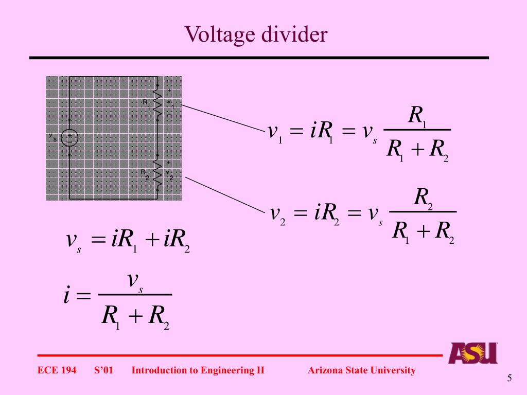
For a voltage divider, understanding how the voltage gets divided across the resistors is directly linked to Ohm's law. Let's consider the current flowing through the circuit. Since the resistors are in series, the same straight resistive track. The output voltage is adjusted by sliding the wiper, typically controlled by
What is a Voltage Divider? A Comprehensive Guide Circuit Diagram
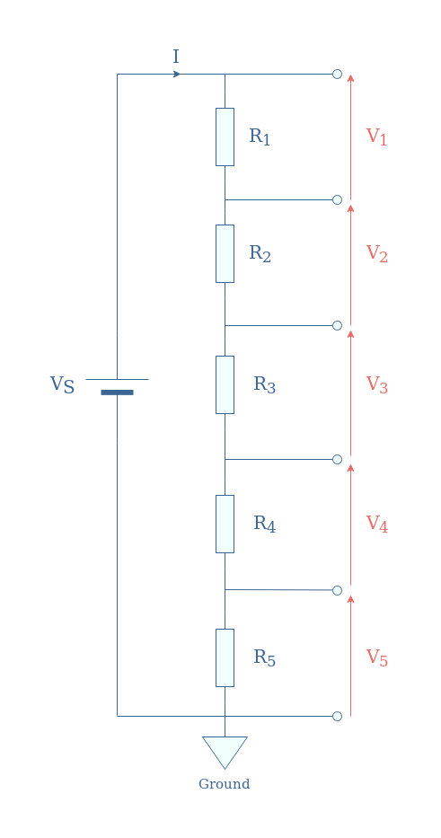
Once you understand how a voltage drops over a resistor, you're about halfway done with understanding a voltage divider. If you need a voltage lower in your circuit than the voltage that is provided by your power source, you can use a voltage divider. a potentiometer is a voltage divider that changes the resistance values depending on A voltage divider is a simple circuit that can reduce voltage. It distributes the input voltage among the components of the circuit. The best example of a voltage divider is two resistors connected in series, with the input voltage applied across the resistor pair and the output voltage taken from a point between them. It is used to produce different voltage levels from a common voltage source
Understanding Voltage Dividers. A voltage divider is a simple yet powerful circuit that generates a specific voltage output from a higher input voltage. It is achieved using two resistors connected in series across a voltage supply. Vin is the input voltage. R1 is the resistance of the first resistor. R2 is the resistance of the second
10+ Voltage Divider Secrets For Better Circuits Circuit Diagram
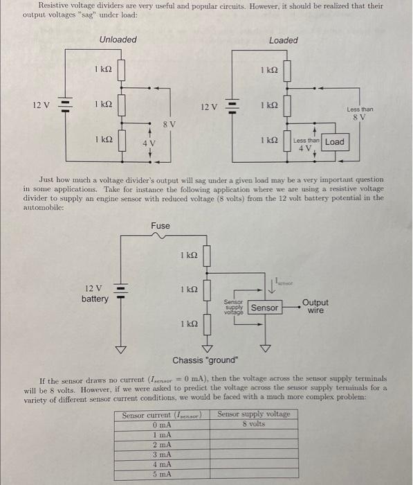
Voltage Divider. The two resistor voltage divider is used often to supply a voltage different from that of an available battery or power supply. In application the output voltage depends upon the resistance of the load it drives. where is the parallel resistance of R 2 and the load resistor R L. For : R 1 = Ω, R 2 = Ω, and V 1 = V,