Measure angles with the MPU6050 accelerometer YouTube Circuit Diagram
BlogMeasure angles with the MPU6050 accelerometer YouTube Circuit Diagram -This is the primary sensor used to sense motion. It only detects accelerations of approximately 3g's. However, this should be enough for the scope of this project. In order to detect motion, the accelerometer values will have to exceed the max or min value for the idle state. Lastly, the code tells the user that the calibration is finished 🔸New component Accelerometer . Overview. The accelerometer, aka 3-axis accelerometer, measures accelerations, changes of velocity with time, and the direction of movement of an object on x, y, and z-axis.It can detect changes in motion, including vibration, rotation, and changes in linear acceleration.They can also detect the direction and magnitude of gravitational forces acting on the object.

Movement Detection. Any change in the location of the accelerometer chip will be registered as changes in the values it sends out. You can use the fact that the numbers registered have changed to detect a movement, or poll the x, y, and z values and make calculations as to in what direction the motion has taken place and by how much it has moved. Motion tracking sensors are used in applications like robotics, gesture recognition, vehicle stabilization, position control in drones/quadcopters, pointing devices, game controllers, and fitness tracking devices. One of the popular motion tracking sensors is MPU6050. It is a six-axis MEMS motion tracking sensor that includes a MEMS accelerometer and a MEMS gyroscope. The sensor also has… The accelerometer we will use is the MMA8452Q, manufactured by Freescale. to detect motion, separate analog-to-digital conversion, and various support hardware. Sparkfun's Accelerometer Breakout Hookup Guide does a great job of describing how to hook up the accelerometer in general (see below). It also provide a nice set of example
Arduino MPU6050 Motion Detection Circuit Diagram
- First, the algorithm "calibrates" the sensor getting 50 samples and using the average as the offset - Subtracts the offset from the accelerometer value - Stores the current value of accelerometer - Makes comparisons using the speed in order to detect the direction I think I'm doing something wrong, because doesn't works well.

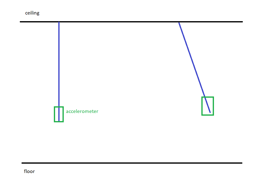
The accelerometer may be used in other ways too - for example, it can be used to detect any device motion. Then the values of the X, Y and Z axis motion can be converted, using math, into angles, magnitude of the movement, and other values. Accelerometers and gyro sensors are both used to detect motion, but they measure different aspects. Accelerometers. Accelerometers measure linear acceleration experienced by an object. They detect acceleration when an object transitions between a stationary state and a moving state, or changes direction or speed. combines a three axis ADXL335 accelerometer with a two axis IDG500 gyroscope. For now we'll just use the accelerometer. A three axis accelerometer detects linear accelerations in three perpendicular directions. If it helps, picture a ball inside a box with pressure sensitive walls. As you shake the box around, the ball presses
